Title here
Summary here
Summary: Crimp, heat-shrink, and verify each run before you ever climb a ladder.
This section covers how to handle the wiring between the light strands.
There is going to be some overlap here between this section and others (puck-tracks, before-you-install-anything, primary-wiring) because there are so many circular dependencies, but the focus on this one is about installing the actual puck lights.
Let’s start with the easy and obvious: the strands come from the factory with xConnect connectors on each end. Assuming you bought the same ones as me of course. Another common alternative that you’ll see is Ray Wu. They’re essentially the same thing and either one is good, but they are incompatible with each other without using an adapter. Regardless of which one you get, make sure you’re getting the same for everything.
I don’t think you need a tutorial on how to put two ends together and twist a nut/locking collar, but there are a few things that will save you time here:

Whether you’re using pigtails that you bought separate, or you’re repurposing factory connectors that you cut off the end of a strand, you’ll find yourself splicing a lot of xConnects. It’s obviously important that you connect the correct wires so that your positive, negative, and data are going to the correct pins. Failing to do that right will end poorly for you.
Purpose-built pigtails will have wire colors that you can use to easily distinguish which cable goes to which connector (although it’s still a good idea to use a multimeter and test one from each batch you get to make sure they’re what you expect).
For ones that you cut off a strand, you can use the labels on the wire jacket to line things up correctly.
With 10 pucks per puck track and 10 pucks per strand, you’ll be bothered when the indexing gets off and you don’t have a strand finish at the end of track (if you’re anything like me at least). This is completely inevitable unless you’re doing a perfectly straight run with no transitions of any kind.
When the index does get off and your strand doesn’t line up perfectly with the end of a track, you have a decision to make:
Just mate your xConnect wherever it falls in the track and keep going.
Pros:
Cons:
Pros:
Cons:
I did both depending on external circumstances of where I was on the roof. Most of the time I chose not to fix it and just kept going. Once installed, you’d never know.
Each strand of lights is 1 meter long and contains 10 pucks (or 5 if you got that instead). You’ll need to splice the wires any time you’re going around a corner, passing through a soffit, or just need a custom length of any kind. I have 75 butt splices left from a pack of 200 so if your house is anything like mine… you’ll be doing this a lot.
In 99% of cases where I needed a splice, I used red (22-16 AWG) heat shrink butt splices. They’re super durable, have a strong hold on the wires, have built in strain relief, and they’re water tight. It basically doesn’t get better for this type of install.
The downsides are that they aren’t flexible, you’ll often have to crimp a wire “in situ” which means you need to bring all the tools (and a heat gun) up the ladder or to wherever you are, and they’re just barely too narrow to use with 12 AWG wire.
My primary wire used two gauges: 12 AWG for the long 2-wire power injection runs and 14 AWG for 3-wire runs. I had no problem getting the 14 AWG wire in to the butt connectors as long as I didn’t try twisting it or anything. Simply strip the wire, insert it straight in to the butt connector, and I was good to go. The reason this matters is what you’re connecting to on the other side: the xConnect pigtails and the wire strands themselves are 20-18 AWG, so you need a connector small enough to properly hold that.
The only place where this didn’t work for me was to connect the 12 AWG 2-wire power injectors down to the small wire. The 12 is simply too big to get in the red butt connectors. Aside from getting a bigger butt connector and hoping you can make the small wire crimp in it correctly, you have two other options: soldering or Wagos.
Soldering is my preferred choice when doing splices in general. Any indoor LEDs I’ve done are all soldered. In this case though, I didn’t like the idea of trying to solder a 12 AWG wire to a 20 AWG wire while I’m 25’ up a ladder on the side of my house. It just wasn’t going to do.
For the few spots where I couldn’t use butt connectors, I used inline Wagos. These are absolutely perfect for connecting different sizes of wire, and they’re super easy. The caveat here is that they aren’t rated for outdoors, and they definitely can’t get wet. But for the places I needed it, they were going to be inside of the soffit and not exposed at all.
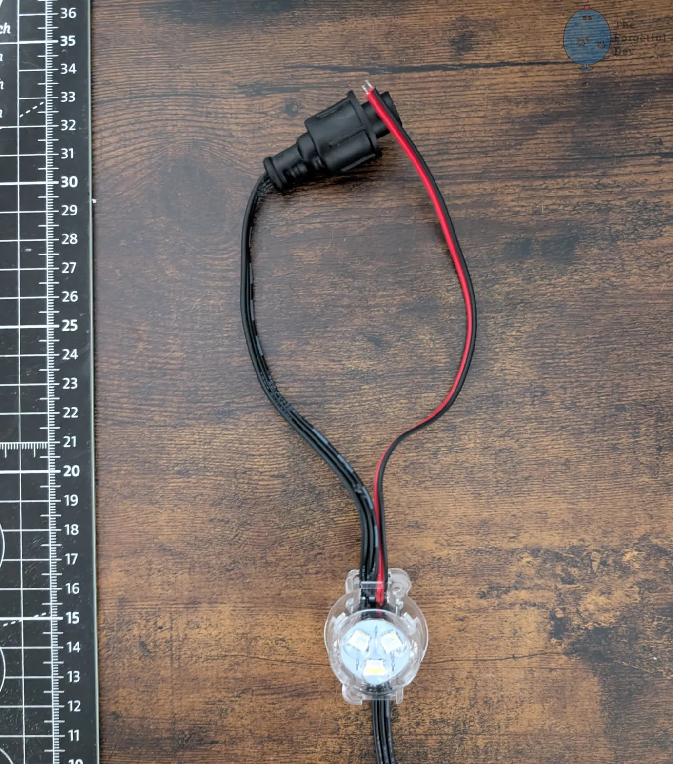
Some number* of the puck strands that you get will have an extra red and black wire at the end. If this is your first experience with smart LEDs then you may not know that these are designed to make power injection easier.
*I say “some number” because there isn’t a count listed from the manufacturer. You’re told how many total strands you’ll get, but not how many will have these injection wires. From having talked to others it seems it varies wildly on how many you’ll get. I personally had like 25 out of the 92 total strands.
Rather than having to use an xConnect splitter (although the kit comes with those too), you can connect your power injection runs directly to those wires. I only had 4 power injections total, and 2 were the ones at the ends of each segment so I just injected through the xConnect at the end of the strand, so I had no use for the ~25 of them that I was sent.
The problem here is that you can’t just throw them in the track as they are or you’ll cause a short, but you’ll still need to use them as they count towards the total number of strands in the kit.
The easiest way to deal with this is to prioritize making those strands the ones you cut up when you need to extend the wire. I figured I’d rather cut these ones up than the ones that don’t have extra wires hanging off. Although if you need to re-use the factory xConnector at the end of the strand then you’ll be back in the same boat.
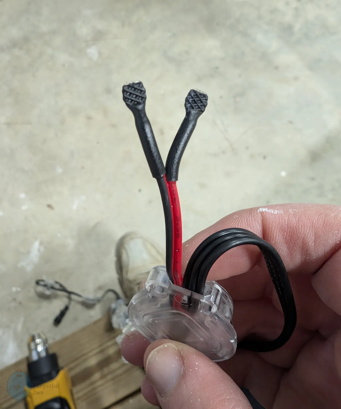
The next best option is to cut the exposed wire ends off, then separate the wires from each other and ensure the ends aren’t exposed. There are a number of ways to do this, but I chose to heat shrink each side separately. And while the heat shrink tubes were still hot, I crimped them with pliers to completely seal the ends.
To actually use the power injection wires, you simply need to connect your power injection primary wires to the red and black wires at the end of the strand using the same method you would have used to attach a pigtail to the end of the primary wire. That’s discussed in detail elsewhere.
When you’re putting butt connectors on your wire you may want to stagger them on some occasions.
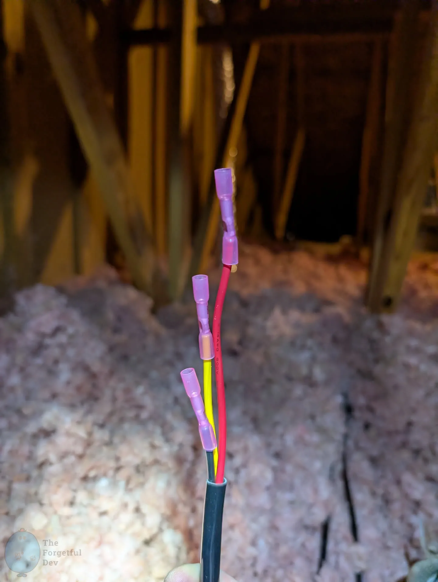
The primary reason for doing it is if you need to get the wire through a hole that is too small for all 3 connectors to be side-by-side. I only did this in a few select locations because usually the extended unbendable section was the bigger problem.


