🛑 This guide is a major work-in-progress. There are missing details, missing pictures, missing articles, and it isn't properly organized in a lot of places. I'm continuing to update it daily, but I've decided to publish what I have so the community can start giving input.
This page was last updated: December 19, 2025 @ 3:01 PM
Mount & Wire the Components
We’re finally here… the fun is about to begin!
From your dry layout, you should have a good idea of how you want to mount everything in the box. All that’s left to do is to actually do it!
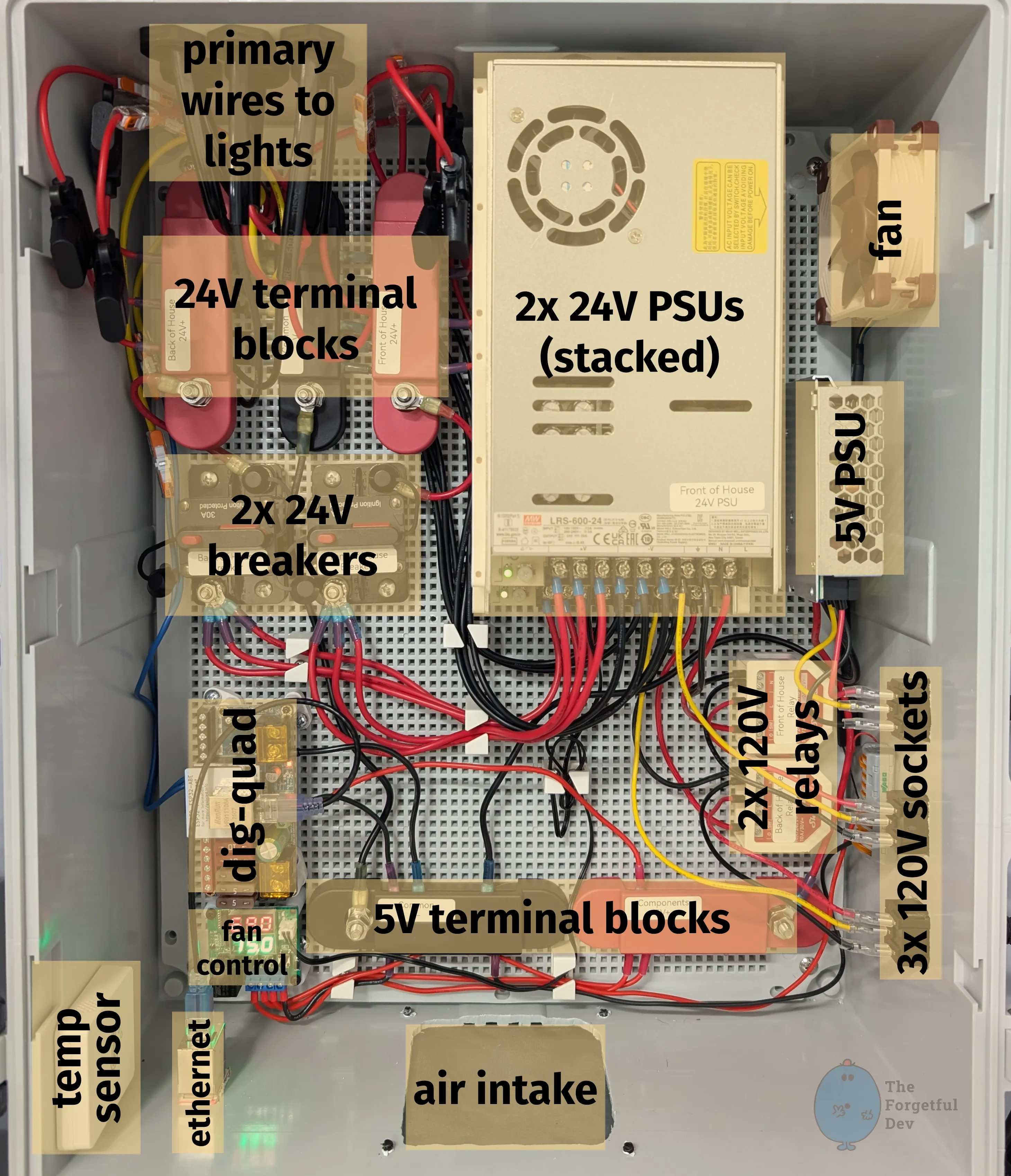
My Layout in Detail
Components highlighted if you want an idea of how I did it.
Here is my layout with the various components highlighted.
Come Take a Tour
I’m going to walk through my layout going from 120V high-voltage input through to light output. We’re starting at the bottom right and will end at the top left, although we may have to make a few circles and u-turns to get there.
High-Voltage 120V AC Components
3x 120V sockets
These allow me to connect 3 computer-style cables to the outside of the box. Keeps it clean and modular.
2 of them connect to the Shelly relays (line) and to the 2x 24V PSUs (neutral and ground)
There are far less expensive options than Shelly, but I like their products and it also allows me to monitor and control things from Home Assistant
See details in the parts-and-materials section if you want to use a standard relay board and the relay trigger built in to the dig-quad (and for additional details on why I didn’t do that beyond me wanting smart relays)
The 3rd connects to the 5V PSU
2x 120V relays
These are the relays that allow me to only power the 2x 24V PSUs when the lights are actually on
2x 24V PSUs
These are stacked (with a gap between them) to save space in the box
They convert 120V AC to 24V DC
Low-Voltage 24V DC Components
2x 24V breakers
All 3 V+ outputs from each PSU connect to each breaker
📝
It's critical that you label everything so that you don't cross any streams here.
The PSUs are only designed to run at full power by spreading their load across all terminals; that’s why you need to bond all 3
These breakers are here as a safety measure to not overload the PSU, but they also provide a convenient way to kill power to the lights if I have to
Breakers can just be reset while a fuse would have to be replaced
🦺
I've received a comment or two that these breakers aren't ideal (no safety rating and likely oversized). I'm exploring replacements.
24V terminal blocks
2x red blocks – 1 each for V+ from each PSU (via each breaker)
⚠️ Seriously… label this stuff so you don’t screw something up
1x black block for common ground
⚡
Ground needs to be shared between all DC components (including 24V and 5V). It should NOT be shared with 120V AC.
12 AWG 2-wire and 14 AWG 3-wire heading off to do their jobs (power and data to the lights)
Each one has its own appropriately-sized fuse (details on that covered in the primary-wiring section)
Low-Voltage 5V DC Components
5V PSU
5V PSU stays powered on all the time so that the dig-quad, fan controller, and fans always have power
5V terminal blocks
These aren’t expensive, but this is an example of “upgraded because I wanted to.”
There aren’t many 5V components. I could have easily done this with a few Wagos or maybe even directly off the PSU itself, but I wanted to have matching terminal blocks. It also makes adding/moving/removing components easier and you already know how important that is to me.
Dig-Quad
My chosen WLED controller
I have the ethernet add-on board as well
Fan control and fan
Small board with a remote temp sensor and relay.
You have to set what temp you want the relay to turn on and off at
💡
This unit can be used for heating or cooling. Make sure yours is in cooling mode or it will do the opposite of what you expect. You got that figured out in a previous section when testing your components though, right?
It also displays the current temp
The temp sensor is attached to the case of the top 24V PSU
The fan is connected to the relay on the fan controller
I have it setup already to be able to install a second fan if this one turns out to not be enough when temps in my garage are warmer. So far it’s been perfectly fine.
Misc
Zigbee temp sensor so I can monitor the temperature in Home Assistant and get alerts if something is going poorly
3d printed ethernet keystone jack to keep things neat
Fresh air intake with screen to keep junk out
Tips You Should Follow
Label Everything
Ok, it’s probably overboard to add terms like PSU to the label for the PSU and Breaker to the label for the Breaker. I’m the only one working on this and I know what those components are. I just like doing that.
But what IS important is you label things based on what section they’re for and what voltage they’re meant for (when relevant).
You don’t want to accidentally connect your 120V relay to your dig-quad (hard to do but totally possible), or accidentally combine your 24V+ terminals between the two PSUs (not hard to do at the terminal blocks where your primary wires are connected), or even something as simple as accidentally powering your 5V fan controller via your 24V PSU (very easy to do…).
Just label things, ok? Geez.
Be Willing to Throw Wires and Connectors Away
I mean, don’t throw them away just because… but be willing to do it when your initial layout needs to change.
A big part of clean builds is accepting that you’ll cut a wire too short, crimp something crooked, or realize you want to move components around. I made an effort to not fully wire everything up until I was sure I was happy, yet I still threw away as much wire and connectors as what ended up in the final box. Maybe even more if I’m honest.
Redoing a run takes minutes and costs pennies. Living with a wire I hate just makes me angry.
💡
To be clear, I'm not encouraging you to be wasteful. Hell we're like 20 pages in to this tutorial and I've spent most of it talking about planning ahead. But just know that you're going to have to redo things if you want a nice clean look. That's all I'm saying.
Test Often While Assembling
Iterative testing is extremely important here. I would power up the box regularly during the build to confirm polarity, check relays, test the controller outputs, and make sure nothing smelled like burning electronics.
💡
It's better to find out you wired something wrong when there are less components to fry.
It's also way nicer to be able to say "this worked fine before I installed that last component, let me check that one" rather than "I just assembled everything and none of it works. What's wrong?"
How To
Cut Holes in the Case
The case is made of fiberglass and is easy to cut, but having a steady hand helps.
For smaller cutouts (holes for socket mounts and keystone jack) I simply used a dremel with a multipurpose cutout bit (they look like drill bits but are designed to cut sideways).
For larger cutouts (intake hole and fan hole) I used a drill in the 4 corners first, then I used the dremel like before. The holes just help keep things neat.
💡
It's a bit over the top but I designed and printed templates for the intake and fan cutouts. I put blue painters tape on the case to protect it, used the template to draw the exact cutout I wanted, then drilled and dremeled.
Mount the Whole Thing to the Wall
Mounting this box wasn’t hard, but just know that it requires a really long screwdriver (or long extensions if using a drill/driver).
The clips that attach to the box and then to the wall don’t stick out very far. That makes for a nice clean look, but the depth of the box means you can’t really get in there to screw the brackets to thew all without having a shaft long enough to clear the box depth.
What I Would Do Different / Mistakes I made
I know where my second fan will go, I pre-wired so it’s ready to pop in, and I even have the fan already. However, I didn’t make a cutout in the box because I didn’t want an unnecessary hole for no reason. But I know that if I ever do need to add it, it’s going to be a huge pain to take the box down, take everything out, cut it, then put it all back. I kind of wish I had just done it already.
I placed the 120V sockets on the side with the intention of using angled power cords (just looks cleaner). What I failed to account for was that the top one would block the middle connector, and the middle would block the bottom. 🤦 I didn’t want to have stray holes in the box so I just left them and used straight cords instead.
I spent a lot of time trying to make the original relays I bought work how I thought they should. But even before I started I knew I’d probably want smart relays in the future. I should have just gone for the smart relays in the first place.