Summary: Mock the layout, separate voltages, and test constantly before you seal the box.
🛑 This guide is a major work-in-progress. There are missing details, missing pictures, missing articles, and it isn't properly organized in a lot of places. I'm continuing to update it daily, but I've decided to publish what I have so the community can start giving input.
This page was last updated: December 19, 2025 @ 4:01 PM
Diagram & Dry Layout
Before installing a single component, I drew a wiring diagram and then dropped all the parts into the empty enclosure. Power supplies, controller, relays, terminal blocks, fan, everything. I moved them around until the wiring paths made sense.
⌛
Hopefully you aren't like me... it took me days to get a layout I was happy with. And I still made small changes several times after.
My Goals for the Enclosure
I wanted the control box to be clean, serviceable, and predictable. I’ve built enough electronics projects to know that the mess you tolerate on day one becomes the nightmare you deal with six months later. So I approached this one with a few guiding rules: keep high and low voltage separated, make the wiring obvious (can easily see what is doing what), allow for clean airflow, avoid routing wires behind the mounting plate, and leave room to adjust things later.
This page goes through how I laid out the components in my enclosure and why I did it this way.
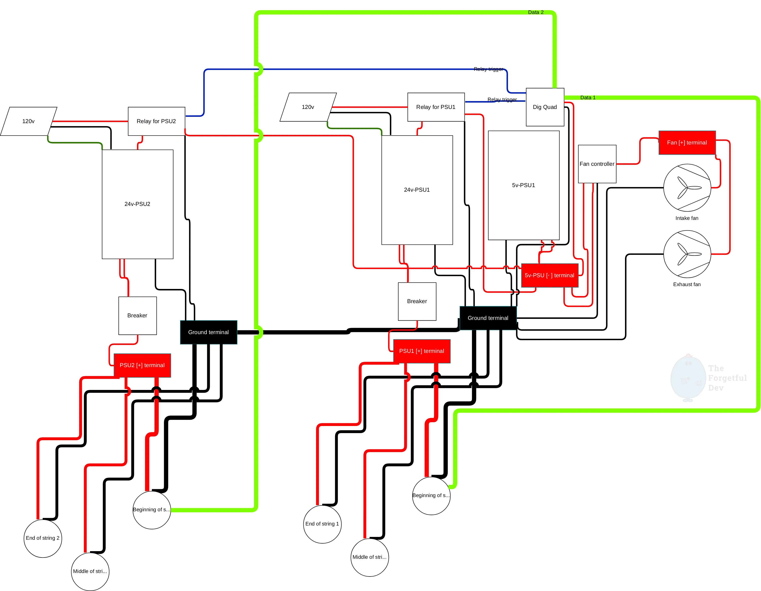
Diagram
After I tested components but before I actually started laying them out, I created a quick wiring diagram (I like to use draw.io for this type of thing).
My initial wiring diagram. Looks a bit like mom’s spaghetti.
For me the point was to have a visualization of what needed to connect to what. It was useful as an actual wiring diagram later, but it also gave me a mental model so I could start getting an idea of how I’d want to lay things out based on what needed to connect.
💡
It would be even better if I had laid out the wiring diagram the same way I wanted to layout the control box, but I prefer doing that part with my hands and the actual products.
Dry Layout
The main thing I figured out, checked, and tested during the dry run:
Would the PSUs fit…
They did, but not how I had originally hoped/planned. I ended up 3d printing a dual mount to get a layout I liked.
How can I isolate high-voltage AC from low-voltage DC wiring (as much as possible)
Where was wiring going to enter/leave the box
How could I minimize wiring within the box
Keep the PSUs at the top because heat rises
Would I be able to get a screwdriver in the tight spots later
Did the layout look balanced rather than random
Keep the two runs (front of house and back of house is what I called mine) symmetrical but separate to prevent accidentally connecting things wrong
Would I have enough room to run my wires
💡
Don't forget that you need room beyond just the components. The wires themselves need to be installed in those components and they'll stick out some. Especially thicker wire like 14 and 12 AWG.
Why I Didn’t Run Anything Behind the Mounting Plate
Some people tuck wiring behind the mounting plate to keep the box looking clean. I chose not to. I wanted full access without having to unmount the whole thing. If a fuse blows, if a controller dies, if I want to add another PSU later, I can do it without pulling the whole thing down or fishing behind the board.
The tradeoff is more visible wiring, but with clean routing it still looks tidy.
💡
I also used 3d printed wire channels (and velcro straps in some places) rather than zip ties holding the wires down to the plate like you see a lot. I think those installs look AMAZING, but I've spent a lot of my career in data centers. The cleanest racks filled with zip-tied cables are the worst when you need to troubleshoot/replace/add cables.
Standoffs Everywhere
Pretty much everything in the box sits on plastic standoffs:
They give me room to run wires underneath those components when it makes sense to do so
They let me slightly adjust spacing between components without remounting everything
They keep bare PCB backs from resting on the mounting plate
The plate is plastic so it’s technically safe from an ESD perspective, but that doesn’t mean it won’t damage the board
I had a combination of store-bought ones and 3d printed ones. I designed the 3d printed ones after realizing the dig-quad needed M2.5 mounting screws (which was too small for the standoffs I had).
What Now?
Once you’re happy with your dry layout, or as happy as you can be, it’s time to actually start installing things! It’s good to have a plan, but you’ll certainly find things you need to change or move while you’re actually mounting and wiring everything. So let’s get to it!