Title here
Summary here
Summary:
If you have been following along then you now have your printer to a point that things are wired up, the BananaPi and SKR Pico are connected, and you can access the fluidd/mainsail UI without any errors. Now the fun begins… seeing your printer move for the first time!
This guide doesn’t cover wiring in detail, but it is important that you have your A/B (aka X/Y) motors plugged in before you continue or you’ll just get errors. Every motor is different so how mine is wired won’t necessarily be how yours should be wired. But you knew that already… right?
However, to save some trouble, you should have:
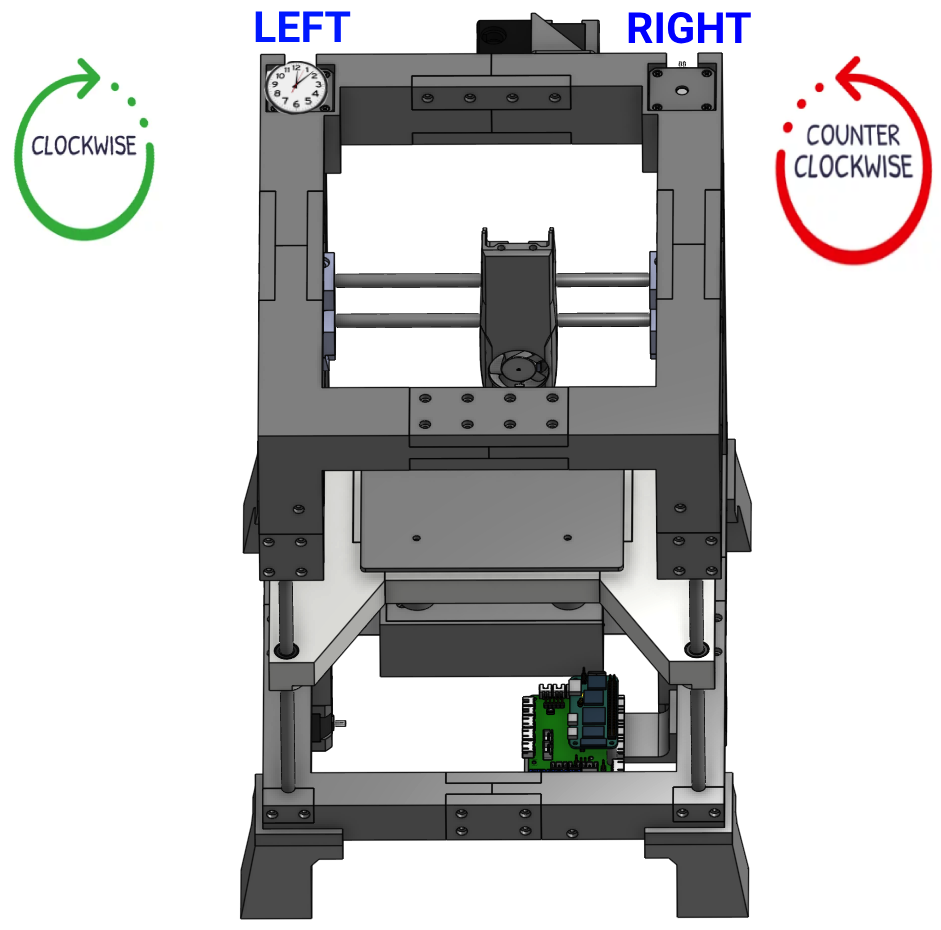
Y plug on SKRX plug on SKR picoBecause we’ll be talking about left/right and clockwise/counter-clockwise, it’s important to establish our perspective. Like a sane person, I’ll be treating everything as if we’re looking at the front of the printer from up above. Even still, it can be confusing for some to understand “clockwise” for the motor shaft when it’s actually pointed down. Just imagine there’s a little clock sitting on top of the motor, and visualize what direction the shaft is moving underneith.
Matt has a completed printer.cfg published on GitHub, but I recommend building your printer.cfg up in stages. This allows you to get individual pieces established and working, rather than trying to troubleshoot the whole cfg at once. Not to mention that Matt’s config is written for his specific printer and is for once the printer is fully working. I highly suggest you follow my process, rather than copy/pasting his whole config at once. You’ll learn more this way, and be in a better place to troubleshoot when needed.
I use both Fluidd and Mainsail on my builds, and I like them both. Matt’s videos initially mention Fluidd so I’m sticking with that for this guide. If you’re using Mainsail instead then the steps will be nearly identical, but the screenshots and printer.cfg won’t match exactly.
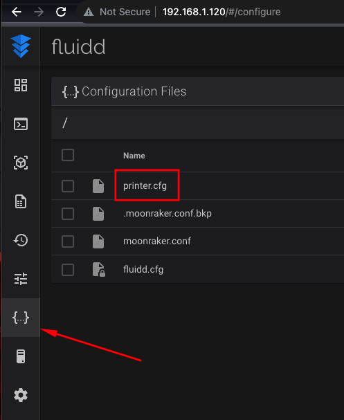
Reminder: you access fluidd/mainsail by going to the IP address of your BananaPi in your web browser. Then click on the configuration icon on the left side and click on printer.cfg to open it in the editor.
If you have been following along with my guides then your printer.cfg should currently look like this:
[include fluidd.cfg]
[virtual_sdcard]
path: /home/klipper/printer_data/gcodes
on_error_gcode: CANCEL_PRINT

[mcu]
serial: /dev/ttyS3
restart_method: command

[printer]
kinematics: none
max_velocity: 1000
max_accel: 1000
Update it so it looks like this:
[include fluidd.cfg]
[virtual_sdcard]
path: /home/klipper/printer_data/gcodes
on_error_gcode: CANCEL_PRINT

[mcu]
serial: /dev/ttyS3
restart_method: command

[printer]
kinematics: corexy      # tell klipper it's a corexy
max_velocity: 100       # these are all intentionally slow for initial testing purposes
max_accel: 1000         # ^
max_z_velocity: 15      # ^
max_z_accel: 50         # ^

[force_move]
enable_force_move: true     # allows us to move the motors without homing

[stepper_x]
step_pin: gpio11
dir_pin: gpio10
enable_pin: !gpio12
rotation_distance: 40
microsteps: 64
endstop_pin: tmc2209_stepper_x:virtual_endstop
position_min: -1
position_endstop: 157
position_max: 157
homing_speed: 50
homing_retract_dist: 0

[tmc2209 stepper_x]
uart_pin: gpio9
tx_pin: gpio8
uart_address: 0
run_current: 0.8
stealthchop_threshold: 999999
diag_pin: ^gpio4
driver_SGTHRS: 115
interpolate: true

[stepper_y]
step_pin: gpio6
dir_pin: gpio5
enable_pin: !gpio7
microsteps: 64
rotation_distance: 40
endstop_pin: tmc2209_stepper_y:virtual_endstop
homing_retract_dist: 0
position_min: 0
position_endstop: 174
position_max: 174
homing_speed: 50
homing_positive_dir: true

[tmc2209 stepper_y]
uart_pin: gpio9
tx_pin: gpio8
uart_address: 2
run_current: 0.8
stealthchop_threshold: 999999
diag_pin: ^gpio3
driver_SGTHRS: 100
interpolate: true

[stepper_z]
step_pin: gpio19
dir_pin: gpio28
enable_pin: !gpio2
microsteps: 16
rotation_distance: 8
full_steps_per_rotation: 200
endstop_pin: tmc2209_stepper_z:virtual_endstop
#position_min: -6
position_min: -21
position_max: 140
homing_speed: 4
position_endstop = 0.650
homing_retract_dist: 0

[tmc2209 stepper_z]
uart_pin: gpio9
tx_pin: gpio8
uart_address: 1
run_current: 0.7
diag_pin: ^gpio25
driver_SGTHRS: 70
stealthchop_threshold: 999999
Click Save & Restart. Verify there are no errors and that klipper/fluidd reconnects to your printer.
We’re now ready to send some simple commands to the A/B motors to make sure that:
You will send the following commands using the console in Fluidd, and observe what the motors do. Reminder that for clockwise/counter-clockwise, it’s from the perspective of you looking down at the motors from up above. Check the screenshot at the top if you’re confused.
FORCE_MOVE STEPPER=stepper_x DISTANCE=300 VELOCITY=30 ACCEL=300
Expected: the right motor should rotate clockwise
printer.cfg under the [stepper_x] section, change dir_pin: gpio10 to dir_pin: !gpio10. Click Save & Restart and then repeat the test.FORCE_MOVE STEPPER=stepper_x DISTANCE=-300 VELOCITY=30 ACCEL=300
Expected: the right motor should rotate counter-clockwise
FORCE_MOVE STEPPER=stepper_y DISTANCE=300 VELOCITY=30 ACCEL=300
Expected: the left motor should rotate clockwise
printer.cfg under the [stepper_y] section, change dir_pin: gpio5 to dir_pin: !gpio5. Click Save & Restart and then repeat the test.FORCE_MOVE STEPPER=stepper_y DISTANCE=-300 VELOCITY=30 ACCEL=300
Expected: the left motor should rotate counter-clockwise
Our previous tests moved one motor at a time. Despite being labeled stepper_x and stepper_y, if you had the belt connected then the printhead would have actually been moving diagonal. Let’s test movement of both motors now.
SET_KINEMATIC_POSITION X=50 Y=50 Z=50
G91
G1 x100 F1000
Expected: both motors turn clockwise at the same time
SET_KINEMATIC_POSITION X=150 Y=50 Z=50
G91
G1 x-100 F1000
Expected: both motors turn counter-clockwise at the same time
Pretty interesting to see both motors turn despite only telling it to move on one axis, right? Now let’s repeat for Y.
SET_KINEMATIC_POSITION X=50 Y=50 Z=50
G91
G1 y100 F1000
Expected: Left motor turns counter-clockwise, right motor turns clockwise
SET_KINEMATIC_POSITION X=50 Y=110 Z=50
G91
G1 y-100 F1000
Expected: Left motor turns clockwise, right motor turns counter-clockwise
Completing all those tests without the belts on allows for much easier troubleshooting since it’s clear what the motors are doing. Once they’re done, you are ready to string and tighten the belt!
When your belt is routed and tightened, physically move the printhead to the middle of the gantry and ensure the bed is low enough that the printhead won’t hit it. And then…
SET_KINEMATIC_POSITION X=50 Y=50 Z=50
G91

G1 x10 F1000    # should move to the right
G1 x-10 F1000   # should move to the left
G1 y10 F1000    # should move towards the back
G1 y-10 F1000   # should move towards the front
You really shouldn’t have any failures here if you completed all the previous steps. If things aren’t moving in the correct direction, or if they’re moving diagonal, take the belt off again and start back at the top.
Now let’s move on to getting the Z axis going!
