Title here
Summary here
Summary:
It turns out it’s a requirement to move in the Z-axis if you want to print in 3d rather than 2d. Let’s get that going now!
printer.cfg is in the state it was left in at the end of that guide.One important thing to understand about the SKR Pico is that while it has two separate outputs for two Z motors, they share the same driver. That means the power and everything is split in two. Typically the Z motors don’t require nearly as much power as A/B motors because they don’t move as much, but this is just something to be aware of.
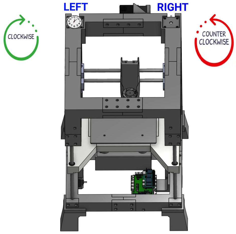
Just like the A/B motors, it’s important to establish our perspective. Like a sane person, I’ll be treating everything as if we’re looking at the front of the printer from up above. Keep in mind that the Z motors are mounted facing up, so clockwise/counter-clockwise is reversed from the A/B motors which face down. Just look at everything from up above.
We’re now ready to send some simple commands to the Z motors to make sure that:
You will send the following commands using the console in Fluidd, and observe what the motors do. Reminder that for clockwise/counter-clockwise, it’s from the perspective of you looking down at the motors from up above. Check the screenshot at the top if you’re confused.
SET_KINEMATIC_POSITION X=50 Y=50 Z=10
G91
G1 Z20 F100
Expected: both motors should rotate counter-clockwise, and the lead screws should not be wobbling at all.
printer.cfg under the [stepper_z] section, change dir_pin: gpio28 to dir_pin: !gpio28. Click Save & Restart and then repeat the test.SET_KINEMATIC_POSITION X=50 Y=50 Z=30
G91
G1 Z-20 F100Expected: both motors should rotate clockwise, and the lead screws should not be wobbling at all.
Completing those tests without the bed allows for much easier troubleshooting since it’s clear what the motors are doing. Go ahead and get the motors installed in the frame now, and thread them in to the tightened lead screw nuts. It doesn’t matter which motor goes on which side.
Using both hands to spin each lead screw at the same time, adjust the bed so you have at least 40mm between the top of the printed bed to the bottom of the top frame.
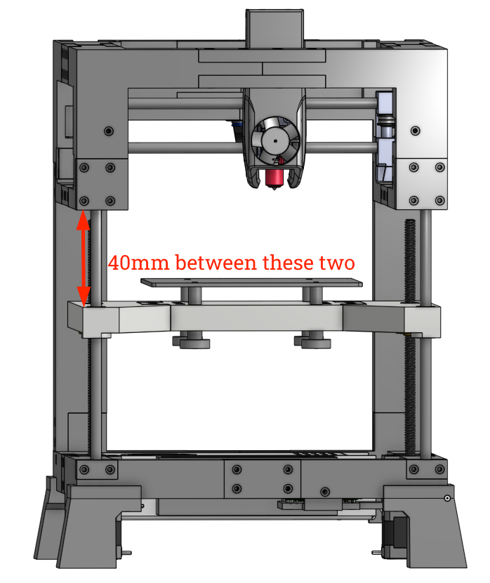
Once you get it to roughly 40mm, use a caliper or something similar to actually measure the distance. This will be important coming up.
SET_KINEMATIC_POSITION X=50 Y=50 Z=40
G91
G1 Z-20 F100
You really shouldn’t have any failures here if you completed all the previous steps, but there is a critical final step: validate your screw pitch. Different lead screws will move the bed a different distance. Re-measure the distance between your bed and the top of the frame and verify it is now 20mm less than your first measurement. If it’s close, that’s fine. If it’s way off, you will need to make changes to rotation_distance. I’m skipping describing that further now so hopefully yours was right! Please @ me on discord if yours wasn’t.
With X/Y/Z all working, it’s time to home your printer for the first time! Spoiler alert: there’s a few things we have to do first…