Title here
Summary here
I recently purchased a Creality Ender 3 Pro and it came with a V4.2.2 mainboard with the GD32F303 MCU. Sadly, this doesn’t include the TMC2225 silent stepper motor drivers which are known to be much quieter.
At first the sound of the printer didn’t bother me but as I started running longer prints, I found the noise of the drivers was haunting me in my sleep (from across the house; behind 2 closed doors).
After doing some research I purchased the V4.2.7 version with TMC2225 drivers (I ordered the official board on Amazon from Cregrant) and it made a HUGE difference. The install took less than 30 minutes and now the fans are practically the only noise I hear. It’s amazing.
I’m not exaggerating: it went from peaking at 57.5dB and averaging 44.6dB while printing, down to peaking at 49dB and averaging 33.8dB. It averages 33.4dB with JUST the fans running; that’s now how quiet it is while printing.
The process to swap from my existing board to the new board was very easy. The steps should be very similar for any version of the Ender 3, but I’m writing this for the Ender 3 Pro.
Unplug power, USB cable, and SD card
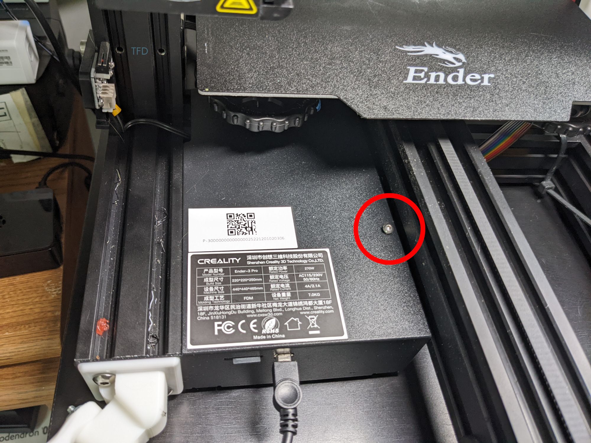
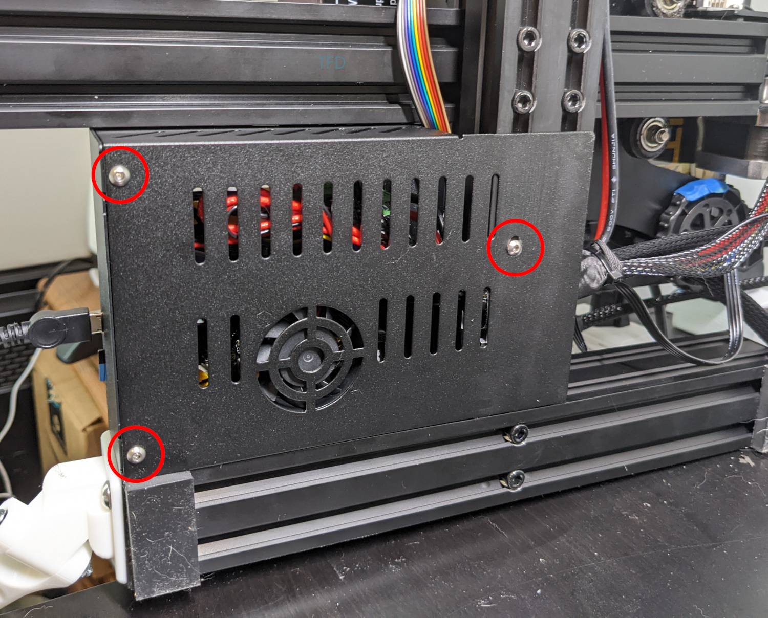
Remove 1x screw on top, then turn on its side and remove 3x screws on bottom
Take note of where it’s installed and then unplug the fan that’s attached to the bottom plate
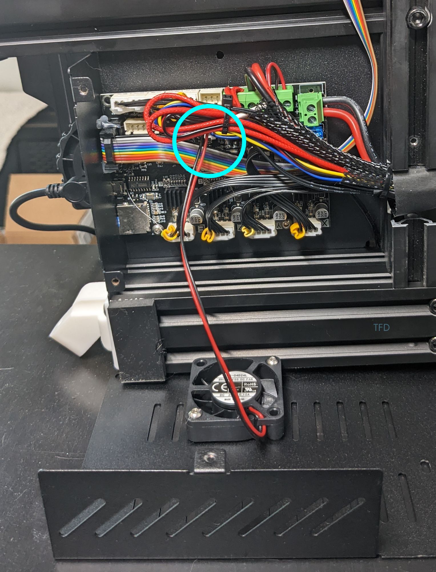
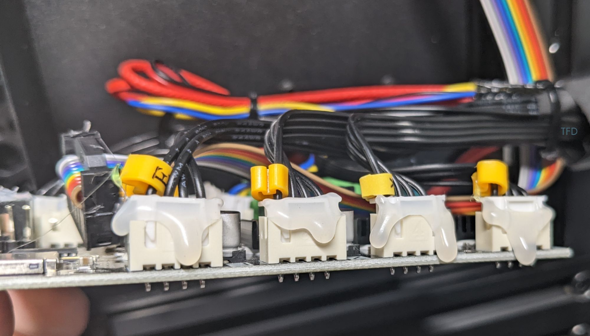
Take lots of pictures of the connections on your current board. Check the cable tags and verify they match what the connectors are labeled on the board itself. If necessary, move the tags to make them match.
Compare the new board to your existing board. It should look almost identical and have the same connectors in the same spots. If that isn’t the case, this may not be the guide for you.

This should leave you with only the power-related cables still connected to the old board
That’s it, you’re done! Power on the printer and verify everything works as expected. At this point you’ll most likely want to update the firmware. My board arrived with Marlin v1.0.1 which I then updated to v2.1.
When relevant, links to Amazon will be affiliate links. As an Amazon Associate I earn from qualifying purchases.


